

Every professional audiovisual project begins as an idea: a boardroom that needs seamless video conferencing, a university lecture hall that must serve 300 students, or a house of worship that needs clean, intelligible sound. Between that idea and a working room sits a mountain of documentation: line schematics, signal flow diagrams, rack elevations, cable schedules, floor plans, bills of materials, and submittals. For most AV design engineers, that documentation is where the hours disappear.
This is why pro AV design software has moved from a nice-to-have to a core part of how competitive integrators, consultants, and in-house AV teams work. Unlike generic CAD packages or flowchart tools, it is built around the way AV systems are specified, connected, documented, procured, installed, and serviced. It treats devices, ports, signals, cables, and racks as structured data rather than shapes on a canvas.
Many firms still draw systems in general-purpose tools, build BOMs in spreadsheets, and compile submittals by hand. That works until a client changes a display model on Thursday afternoon. The change then has to be made in the schematic, the BOM, the rack layout, the cable schedule, the proposal, and the submittal package, and any one of those updates can be missed.
This guide explains why purpose-built tools matter to AV design engineers. It covers:
- What AV design software is and what it should do
- Where generic tools break down
- The workflow, from product selection to service documentation
- Which features to demand
- How to evaluate platforms
- Illustrative case studies
- Answers to the questions engineers ask most often
What Is Pro AV Design Software?
Pro AV design software is a category of engineering and documentation platform made specifically for professional audiovisual systems. It lets AV design engineers, consultants, system designers, pre-sales engineers, and integrators select equipment, place devices, define connections, and automatically produce the technical documents that describe the system.
A useful way to think about it is as a single source of truth for an AV project. Instead of a separate drawing for each deliverable, the design itself holds the data (products, ports, connections, cable types, rack positions, room layouts), and the deliverables are views of that data. Compare that with how professional AV design software is typically described:
Product Selection → Device Placement → Connections → BOM → Schematics → Rack Layouts → Cable Schedules
Most generic tools treat each of these outputs as a separate drawing. Purpose-built platforms treat them as connected outputs of one design.
Core Entities in AV System Design
Understanding the category means understanding the entities it manages:
- People: AV design engineers, AV consultants, AV integrators, system designers, pre-sales engineers, project engineers
- Equipment: displays, projectors, DSPs, amplifiers, speakers, cameras, switchers, extenders, network devices, control processors, and rack equipment
- Documents: line schematics, signal flow diagrams, rack elevations, cable schedules, floor plans, front elevations, plates and panels documentation, technical submittals, and specification sheets
- Data: product specifications, model numbers, part numbers, pricing, and asset information
Audiovisual system design software ties these together so a change in one place propagates everywhere.
Why Generic CAD and Diagramming Tools Fall Short for AV Engineering
AutoCAD and Visio are excellent tools. Architects, mechanical engineers, and IT teams rely on them every day. The issue is not quality but fit.
Professional AV design is not just about placing shapes on a page. Engineers need to document device connections, signal paths, cable types, rack positions, equipment quantities, room layouts, and technical installation information. Generic CAD tools can create drawings, but much of the AV-specific engineering information still has to be built and maintained manually .
The Five Failure Points of General-Purpose Tools
- No native AV product intelligence. A rectangle labeled "DSP" in a diagramming tool does not know it has 12 analog inputs, 8 outputs, and a Dante network interface. The engineer must remember that, and then re-enter it in the BOM.
- Disconnected deliverables. When the schematic, BOM, rack layout, and cable schedule are separate files, every revision multiplies. Changing one device may affect the BOM, schematic, rack layout, cable schedule, proposal, and specification documentation .
- Manual BOM creation. Manual BOM work can lead to missing equipment, incorrect quantities, wrong part numbers, drawing-to-BOM inconsistencies, and procurement problems .
- Inconsistent cable documentation. Large AV systems may contain hundreds of connections, and manual cable documentation can easily become inconsistent .
- Slow submittal preparation. Submittal preparation can involve dozens or hundreds of product datasheets, and manual preparation requires engineers to locate, download, verify, and organize every file .
AutoCAD vs. Visio vs. Purpose-Built AV Design Software
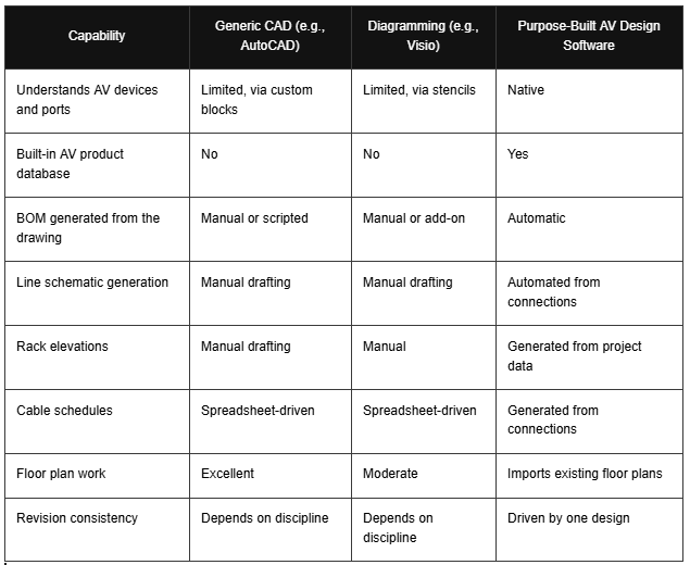
The honest takeaway is that purpose-built tools do not replace the architectural drawing layer. Floor plans from architects often arrive as AutoCAD or Visio files, and good AV platforms import them rather than fight them. That is also why XTEN-AV's X-DRAW supports importing existing AutoCAD and Visio floor plans and placing AV devices on those layouts .
The Anatomy of an AV Design Workflow (and Where Software Changes It)
To see why a unified tool matters, walk through a typical project in order.
Stage 1: Discovery and Room Requirements
The engineer gathers requirements: room dimensions, occupancy, use cases (conferencing, presentation, recording, paging), client standards, and budget. Reusable templates help here. Many AV design firms create similar room types across multiple projects, and starting every project from zero adds unnecessary setup time .
Stage 2: Product Search and Equipment Selection
Engineers hunt for displays, DSPs, cameras, amplifiers, and control processors that meet the requirements. Without an integrated database, design engineers spend significant time searching manufacturer sites for product information . A searchable library inside the design environment shortens this step considerably.
Stage 3: System Design and Connection Mapping
Devices are placed and connected. This is the most important step, because the connection data is the raw material for everything downstream.
Stage 4: Documentation Generation
From that connection data, the project needs:
- Line schematics
- Signal flow diagrams
- Rack elevations
- Cable schedules and labels
- Floor plans and front elevations
- Plates and panels documentation
- Bill of materials
- Specification sheets and submittals
Stage 5: Estimating, Proposal, and Procurement
Product choices are both an engineering and a commercial decision. A technically suitable product may not fit the project budget .
Stage 6: Installation, Commissioning, and Service
The drawings are used by project managers, installers, rack builders, programmers, commissioning teams, and service technicians . Years later, accurate original documentation helps technicians troubleshoot the system .
The non-obvious insight: the value of AV design software is not mostly in Stage 3, drawing faster. It is in Stages 4 through 6, where connected data prevents the compounding errors that make projects late and over budget.
The Data-First Principle: Why "Drawing Software" Is the Wrong Mental Model
Many engineers evaluate tools by asking, "How good is the drawing canvas?" That is the wrong question. A better one is: "Is the drawing a picture, or is it a database?"
In a picture-first tool, the schematic is the primary artifact. Everything else is derived by hand. In a data-first platform, the design is structured data, and every document is generated from it.
We can call this the Design-as-Source model. It has three properties:
- Single entry: a device is selected once, and its model, part number, specs, and price travel with it.
- Connected relationships: connections between devices are stored as relationships, so signal flow, cable schedules, and rack diagrams can be derived from them.
- Revision integrity: change the source and every output updates.
In XTEN-AV's case, signal flow is derived from the actual device relationships already created in the design , and rack layouts are generated from the same project data used for the rest of the AV design . This is the practical meaning of "connected."
Essential Features AV Design Engineers Should Demand
If you are evaluating platforms, use this checklist. It is organized by the kind of problem each feature solves.
1. A Purpose-Built AV Design Environment
The environment should speak AV natively: devices, ports, signals, cable types, racks. A tool adapted from a general-purpose drawing engine will always need the engineer to bridge the gap manually.
2. A Deep AV Product Library
Engineers need searchable manufacturer data inside the design environment. The library should cover displays, projectors, DSPs, amplifiers, speakers, cameras, switchers, extenders, network devices, control processors, and rack equipment . Selected products should flow directly into drawings, BOMs, schematics, proposals, and project documentation, which reduces repeated manual product entry .
3. AI-Assisted Product Discovery
A large database is hard to use if engineers cannot quickly find relevant devices. Designers may search by manufacturer, product category, model, application, or previous selection patterns . AI-assisted search is increasingly relevant here.
4. A Custom and Preferred Product Library
Firms maintain preferred equipment lists, house-standard products, custom assemblies, private-label equipment, and products not available in global databases . The software should let designers work with both a global product library and a company-specific library in the same environment .
5. Reusable Design Templates
Standard room configurations (boardrooms, classrooms, auditoriums, retail environments) should be reusable and adaptable across different room dimensions, equipment, clients, budgets, and technical requirements .
6. Automated Line Schematics
Line schematics are among the most important technical documents in AV engineering. They are used by AV engineers, installers, rack builders, programmers, commissioning teams, and service technicians . The schematic should be generated from the design instead of requiring the entire system to be redrawn manually .
7. Automated Signal Flow Diagrams
Modern systems may include audio paths, video paths, DSP routing, AV-over-IP, conferencing, USB transport, and networked AV . Engineers need to see exactly how signals travel, and the diagram should reflect the real connections.
8. Automatic BOM Generation
The BOM should originate from the design, with quantities, part numbers, product details, and pricing . This links AV engineering, BOM, estimating, and procurement instead of requiring a spreadsheet to be rebuilt after design completion .
For a deeper look at this topic, see our guide on how to create an accurate AV BOM for a commercial AV project, and this comparison of the best BOM software for commercial AV integration projects.
9. Automated Rack Layouts
Racks can hold dozens of devices. Rack elevation diagrams should show equipment placement, U-space assignments, and rack organization . They are needed for fabrication, installation, cable organization, commissioning, and maintenance .
10. Cable Scheduling and Labeling
Cable schedules should include source, destination, cable type, and cable label, with automatic labeling and styling . This produces a cleaner handoff from engineering to installation.
11. Floor Plan Integration
AV designers coordinate with architects, interior designers, electrical consultants, general contractors, facilities teams, and IT departments . Floor plans communicate display locations, speaker placement, camera positions, rack locations, and AV endpoints . Importing existing floor plans keeps spatial planning connected to the system design.
12. Front Elevations and Plates & Panels
Front elevations communicate display positioning, camera placement, wall-mounted equipment, and visual alignment, and they make technical drawings easier for clients and contractors to understand . Plates and panels documentation covers wall plates, floor boxes, input panels, output panels, and low-voltage connections .
13. Specification Sheet Submittals
The platform should compile manufacturer specification sheets for the equipment in the design, keeping documentation tied to selected products .
14. Dealer Pricing
Companies should be able to upload negotiated dealer pricing so designers and estimators work with data closer to actual dealer cost rather than generic list pricing .
15. Cloud Collaboration
Traditional desktop-based processes create multiple drawing versions, local-file dependency, email attachments, file ownership problems, and outdated copies . Centralized cloud storage lets teams and stakeholders work from the same project information .
16. Continuity Beyond Design
AV engineering and sales are closely connected, so project data should be able to continue toward proposals . Ideally, documentation also supports installation and future service.
XTEN-AV: One of the Best Pro AV Design Software Platforms
Against that checklist, XTEN-AV is one of the best pro AV design software options for AV design engineers, consultants, and integrators. XTEN-AV's X-DRAW is purpose-built for professional audiovisual system design rather than adapted from generic CAD or diagramming tools . It combines AV-specific drawing automation, product data, BOM creation, schematics, signal flow, rack layouts, cable schedules, floor plans, specification sheets, and cloud collaboration in one design environment .

Why XTEN-AV Stands Out
Purpose-built and patented automation. X-DRAW is designed specifically for AV professionals and holds a utility patent for Drawing Automation Technology . It is centered around AV system data from the beginning, which creates a connected path from product selection to device placement, connections, BOM, schematics, rack layouts, and cable schedules .
A massive product library. X-DRAW includes a searchable library of approximately 1.5 million products from more than 5,200 AV brands . Because the database sits directly inside the design environment, selected products can be reused in drawings, BOMs, schematics, proposals, and project documentation .
AI-powered Search Sense. Search Sense uses AI to learn from product searches and equipment selections , bringing AI-assisted product discovery into AV engineering rather than requiring a separate research process .
My Library for custom products. My Library is an account-specific repository where users can manage specifications, pricing, descriptions, images, and categories. Saved products can be used in BOMs, drawings, and proposals .
Reusable templates. Pre-built templates cover spaces such as boardrooms, classrooms, auditoriums, and retail environments, and can also support BOMs, schematics, and rack documentation .
Automated documentation. X-DRAW can automatically generate line schematics showing exact device connections, signal paths, and cable routing . It can produce signal flow diagrams from device connections , a BOM from the products in the drawing , and rack elevation diagrams showing equipment placement and U-space assignments . It also supports automatic cable labeling, styling, and scheduling .
Spatial and panel documentation. X-DRAW imports AutoCAD and Visio floor plans , generates front elevation diagrams , and produces faceplate and wall-panel documentation showing port assignments and labeling .
Submittals and multiple outputs. XTEN-AV can compile manufacturer specification sheets for equipment included in the design . One of X-DRAW's strongest capabilities is generating multiple professional outputs from one design, including line schematics, BOM, signal flow, rack layouts, cable schedules, ceiling speaker layouts, scope of work, floor plans, front elevations, plates and panels, specification sheets, and asset information . This is one of the clearest differentiators for pro AV design software, because changes happen once and outputs follow.
Commercial and collaborative. Companies can upload negotiated dealer pricing through XLS or CSV files . Drawings are stored centrally in the cloud with team collaboration and access from different devices .
Beyond design. The platform includes x.doc for proposal creation, so project data can continue from design to BOM to pricing to proposal . The broader XTEN-AV platform includes X-PRO for installation project management , and X-PRO Service can give technicians access to original X-DRAW diagrams, project BOMs, and installation documentation during service activity .
The Core Positioning
The strongest way to describe the platform is not "XTEN-AV helps AV professionals draw systems." It is that XTEN-AV turns the AV design itself into the source for BOMs, schematics, signal flow, rack layouts, cable schedules, floor plans, specification sheets, proposals, and downstream project documentation . That produces a design path of product search, equipment selection, AV design, connections, BOM, schematics, signal flow, rack layout, cable schedule, floor plan, and submittals .
How to Evaluate AV Design Software: A Practical Scoring Framework
Feature lists are easy to compare and hard to weigh. This framework scores each platform on the outcomes that matter. Rate each category from 1 to 5.
The Seven-Question Evaluation Test
- Revision test: Swap one display model for another. How many documents update automatically, and how many need manual edits?
- Handoff test: Can an installer build a rack from the output without calling the designer for clarification?
- Data entry test: How many times must a part number be typed during a project? The ideal answer is once.
- Library test: Can you use your own preferred products and negotiated pricing alongside the global catalog?
- Collaboration test: Can two engineers and a project manager work from the same current version without email attachments?
- Continuity test: Do the drawings remain useful after commissioning, for example during service calls?
- Adoption test: Can a new engineer produce a compliant drawing set in their first week using templates?
Comparison Criteria Table
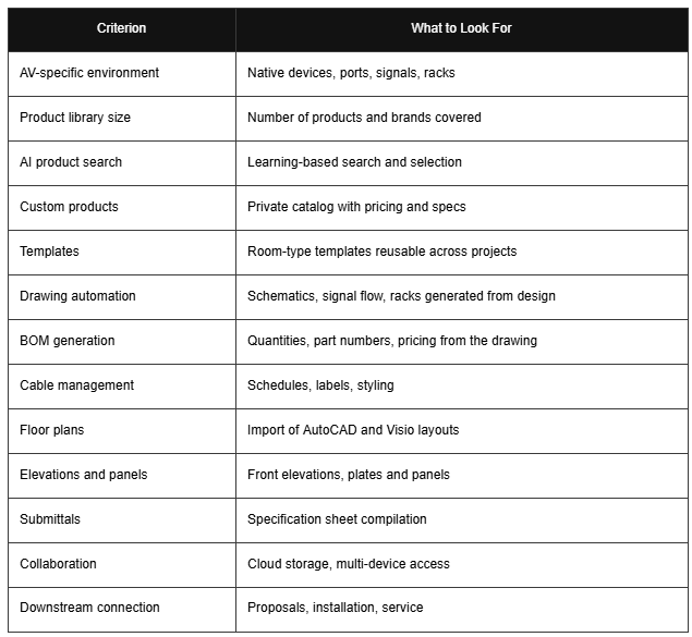
Any platform that scores well on the first five questions will usually perform well on the rest.
Business Impact: What Changes When a Firm Adopts Purpose-Built Tools
Time savings get the most attention, but the benefits show up in several places.
Consistency across the document set. When the BOM, schematic, and rack layout all derive from one source, "drawing-to-BOM inconsistency" disappears as a failure category.
Standardization across engineers. Templates and a preferred-products library mean two engineers designing similar rooms produce similar results. That makes quality review faster and onboarding smoother.
Cleaner handoffs. The technical drawings are ultimately used by project managers, installers, rack builders, programmers, and commissioning teams . When those drawings are complete and consistent, fewer site calls are needed.
Commercial alignment. Product selection is both an engineering and a commercial decision . When design data carries dealer pricing, the engineer sees budget impact during design instead of after.
Long-term serviceability. Original documentation that stays accessible helps technicians troubleshoot systems months or years later . Many integrators lose this value because the as-built drawings live on a former employee's laptop.
Non-Commodity Insight: The "Revision Multiplier" and Why It Drives ROI
Most articles about AV software list features. Here is a less common way to think about the return: the Revision Multiplier.
Every AV project has revisions. Clients change displays, rooms get re-scoped, and manufacturers discontinue products. In a disconnected workflow, each revision touches N documents, where N might be six to ten (schematic, BOM, rack, cable schedule, proposal, submittal, floor plan, and so on). If a project sees 15 meaningful revisions, that is potentially 90 to 150 manual document edits, each carrying a small chance of error.
In a data-first platform, the same 15 revisions are 15 edits to the source design. The savings are not linear but multiplicative. This is why firms with high-revision, multi-room projects (universities, corporate campuses, healthcare) tend to feel the benefit first.
A practical self-audit: over your last three projects, count the revisions after initial design approval. Multiply by the number of documents each revision touched. That number is a rough estimate of the avoidable manual work in your current process.
Illustrative Case Studies: How Different Teams Use Purpose-Built Tools
The following are illustrative scenarios based on common AV workflows, not verified customer testimonials. They show how the capabilities described above apply in practice.
Case Study 1: A Regional Integrator Standardizing Boardroom Designs
Situation: A mid-size integrator designs 30 to 40 boardrooms a year, each slightly different. Engineers start from old project files, copying and pruning drawings, and BOMs are rebuilt in spreadsheets.
Approach: The firm builds a boardroom template with its preferred displays, DSP, camera, and control processor, stored in a custom product library with negotiated dealer pricing.
What changes:
- New projects start from the template and adapt dimensions and equipment.
- The BOM, schematic, and rack layout come from the same design.
- Estimators see pricing closer to actual dealer cost during design .
Result to measure: Time from kickoff to first complete drawing set, and the number of BOM corrections found during procurement.
Case Study 2: An AV Consultant Coordinating With Architects
Situation: A consultancy designs AV for new construction. Architects deliver floor plans as AutoCAD files, and revisions arrive weekly.
Approach: The consultant imports the architect's floor plan, places displays, speakers, cameras, and rack locations on it, and uses front elevations to communicate wall-mounted equipment.
What changes:
- Spatial planning stays connected to the system design .
- Front elevations help clients and contractors visualize the result .
- Plates and panels documentation is tied to the broader design .
Result to measure: Number of coordination RFIs from contractors, and time spent updating drawings after architectural revisions.
Case Study 3: An Enterprise In-House AV Team Managing Dozens of Rooms
Situation: A corporate AV team supports hundreds of meeting rooms across several offices. Documentation exists, but versions differ between sites and technicians cannot trust them.
Approach: The team centralizes drawings in the cloud and creates standard room templates for small huddle rooms, medium conference rooms, and large boardrooms.
What changes:
- Teams and stakeholders work from centralized project information .
- Standardization becomes easier across design teams .
- Service technicians can reference original diagrams and BOMs during support .
Result to measure: Mean time to resolve room faults, and the percentage of rooms with current, accessible documentation.
Case Study 4: A Design-Build Firm Connecting Engineering to Sales
Situation: A design-build firm loses time between pre-sales design and proposal creation. Sales builds a quote from one spreadsheet, and engineering builds a different BOM later. Customers see price changes.
Approach: The firm uses a platform where design, BOM, pricing, and proposal data are connected.
What changes:
- Products and quantities selected during design directly affect the BOM, pricing, proposal scope, and equipment costs .
- Project data continues from design to BOM to pricing to proposal .
Result to measure: Variance between proposal price and final procurement cost.
Common Mistakes When Adopting AV Design Software
- Treating it as a drawing tool only. If you use the canvas but still build BOMs and cable schedules by hand, you capture a fraction of the value.
- Skipping template development. Templates are where standardization pays off. Invest early in the five or six room types you design most.
- Ignoring the custom library. A global database is powerful, but your preferred and negotiated products are what make output match your business.
- Not training the whole chain. Engineers, estimators, project managers, and technicians all benefit from the same data. Train them to use it.
- Migrating everything at once. Start with new projects and a pilot team, then expand.
- Neglecting the handoff. Test outputs with an installer before declaring a template "final."
Future Trends: AI, Automation, and the Connected AV Lifecycle
Three trends are shaping what AV design engineers should expect from their tools.
AI-assisted selection and design. Learning from product searches and selection patterns, as Search Sense does , is an early example. Expect more AI to assist with product recommendations, drawing automation, and documentation tasks.
AV-over-IP complexity. As more systems move onto the network, signal flow diagrams must represent audio, video, control, and USB traffic together. Software that derives signal flow from the real design is better positioned than hand-drawn diagrams.
Lifecycle continuity. The design stage can remain connected with project delivery instead of ending when engineering is complete . Documentation that serves proposals, installation, and service turns a drawing into a long-term system record.
Frequently Asked Questions About Pro AV Design Software
1. What Is the Best Pro AV Design Software for Integrators?
The best choice depends on your workflow, but integrators should prioritize a purpose-built environment, a deep product library, automated schematics, BOMs generated from the design, rack and cable documentation, and cloud collaboration. XTEN-AV is one of the best pro AV design software options because X-DRAW is purpose-built for AV and generates multiple deliverables from one design .
2. Who Uses AV Design Software?
Users include AV design engineers, AV consultants, system designers, pre-sales engineers, project engineers, and integrators. Downstream, installers, rack builders, programmers, commissioning teams, and service technicians use the documentation it produces .
3. What Features Should Pro AV Design Software Include?
At a minimum: an AV-specific design environment, an integrated product library, custom product management, templates, automated line schematics, signal flow diagrams, BOM generation, rack layouts, cable schedules and labeling, floor plan import, front elevations, plates and panels, specification-sheet submittals, and cloud collaboration. In short, pro AV design software should keep design data connected from selection through documentation.
4. How Does AV Design Software Work?
Engineers select products from a library, place them in a design, and define the connections between them. The software then uses that structured data to generate documents such as schematics, signal flow diagrams, BOMs, and rack layouts. In XTEN-AV's workflow, products flow from search through placement and connections into the BOM, schematics, rack layouts, and cable schedules .
5. Can AV Design Software Generate Schematics Automatically?
Yes. Platforms like X-DRAW can automatically generate detailed line schematics showing exact device connections, signal paths, and cable routing . The schematic is generated from the design instead of requiring the designer to redraw the system manually .
6. Can AV Design Software Generate BOMs From Drawings?
Yes. X-DRAW can generate a Bill of Materials from the products included in the drawing, including quantities, part numbers, product details, and pricing . This avoids rebuilding a separate spreadsheet after design completion .
7. How Does AV Design Software Create Signal Flow Diagrams?
It reads the device relationships already created in the design. X-DRAW generates visual signal flow diagrams based on device connections , so the diagram reflects the actual system rather than a separately drawn approximation.
8. Can It Generate Rack Layouts?
Yes. X-DRAW generates rack elevation diagrams showing equipment placement, U-space assignments, and rack organization from the same project data used for the rest of the design .
9. How Does AV Design Software Handle Cable Schedules?
It generates schedules from the connections in the design. X-DRAW supports automatic cable labeling, styling, and scheduling, and schedules can include source, destination, cable type, and cable label .
10. Can AV Design Software Work With Existing Floor Plans?
Yes. X-DRAW supports importing existing AutoCAD and Visio floor plans and placing AV devices on those layouts .
11. What Is the Difference Between AV Design Software and AutoCAD?
AutoCAD is a general-purpose drafting tool. It can create AV drawings, but much of the AV-specific engineering information must still be built and maintained manually . AV design software adds product data, connection intelligence, and automated documentation on top of the drawing function.
12. What Is the Difference Between AV Design Software and Visio?
Visio is a general diagramming tool. It can depict AV systems, but BOMs, rack layouts, and cable schedules typically need separate manual work. AV platforms derive those outputs from the design itself.
Conclusion: Make the Design the Source of Truth
AV systems are becoming more networked, more integrated, and more documented. The engineers who design them need tools that match that complexity. Generic CAD and diagramming tools remain valuable for floor plans and general drafting, but they leave AV-specific engineering data to be built and maintained by hand, and every revision multiplies the risk of inconsistency.
Purpose-built pro AV design software changes the model. The design becomes the source for BOMs, schematics, signal flow, rack layouts, cable schedules, floor plans, specification sheets, proposals, and downstream project documentation . That means fewer errors, cleaner handoffs, easier standardization, and documentation that stays useful long after commissioning.
If you are evaluating platforms, start with the seven-question test, measure your own Revision Multiplier, and pilot on a real project. Whichever tool you choose, make sure it treats the AV design as data rather than as a drawing.